


 Menu
Menu
American Owned & Operated
Committed to supporting American industry and ensuring the highest-quality production standards.
Posted by Bill Hill on

Having covered the basic types of lens configurations, as well as, the mechanical parameters used to define a lens shape, we will now discuss how opticians and fabricators characterize the precision of lens surfaces. If you recall from our article on the surface figure of plano optics, we learned that there is a large difference between the quality of a “commercially” polished surface, i.e. clear and transparent, to those of high-precision specified in waves or fractions of a wave and tested using the principles of interferometry. Obviously, as the level of precision increases, the difficulty in producing the optic also increases which, in turn, affects the cost. It is therefore important to consider the following aspects of lens surface form when weighing the benefits of performance, functionality and price.
Outside of choosing an optical material based on its ability to refract light, the single most important aspect of a lens is the radius of curvature. By combining a material’s optical characteristics with a specific radius on either one or both surfaces, opticians can clearly define how light will behave when refracted by the optic. If you recall from our previous article, the radius of curvature defines the focal length of a lens and can be calculated using the simple lens equation (for thin lenses). From the lens equation it follows that any change in the radius from its designed curvature will adversely affect the desired focal length. In order to control any variation in the focal length, opticians therefore need to define the radius tolerance. The first method is to apply a simple mechanical tolerance, for example, a radius may be defined as 100 +/-0.1mm. In such a case, the radius can vary between 99.9mm and 100.1mm. The second manner is to apply a radius tolerance in terms of percentage. Using the same 100mm radius, an optician may specify that the curvature may not vary more than 0.5%, meaning the radius must fall between 99.5mm and 100.5mm. The third method is to define a tolerance on the focal length, most often in terms of percentage. For example, a lens with a 500mm focal length may have a +/-1% tolerance which translates to 495mm to 505mm. Plugging these focal lengths into the thin lens equation allows fabricators to derive the mechanical tolerance on the radius of curvature.
In practice, optical fabricators use several different types of instruments to qualify the radius of curvature on a lens. The first is a spherometer ring attached to a measuring gauge. By comparing the difference in curvature between a predefined “ring” and the optics’ radius of curvature, fabricators can determine if further correction is necessary to achieve the appropriate radius. There are also a number of digital spherometers on the market for increased accuracy. Another highly accurate method is an automated contact profilometer which uses a probe to physically measure the contour of the lens. Finally, the non-contact method of interferometry can be used to create a fringe pattern capable of quantifying the physical distance between the spherical surface to its corresponding center of curvature.
Power is a measurement of curvature on the surface of an optic and differs from the radius of curvature in that it applies to the micro-scale deviation in the spherical shape of a lens. Consider once more the same radius of curvature defined above as 100 +/-0.1mm. Once this radius is generated, polished and measured, we find its actual curvature to be 99.95mm which falls within the specified mechanical tolerance. In this case, we know that the focal length is also correct since we’ve achieved the correct spherical shape. But just because the radius and focal length are correct, does not mean the lens will perform as designed. It is important to remember that with light, we are working on the scale of nanometers (billionths of a meter) and even the smallest imperfection in the surface form of a lens can adversely affect how the refracted light behaves. In many applications, it is therefore not enough to simply define the radius of curvature but also the consistency of the curvature – and this is precisely what power is designed to control.
Opticians specify power in terms of waves or fringes and measure it using an interferometer. (If you are unfamiliar with the principles of interferometry and how light is used to test for micro-scale deviations in the surface form of an optic, please refer to our previous technical article on interferometry). Again using the same 99.95mm radius mentioned above, an optician may wish to further control the accuracy of refracted light by limiting the power to < /= 1 wave. This means that across the entire radius, there can be no greater deviation than 632nm (1 wave = 632nm) in the consistency of the spherical shape. Adding this more stringent level of control to the surface form assists in making sure that light rays on one side of the lens do not refract differently than those on the other side. Since the goal may be to achieve pinpoint focus of all incident light, the more consistent the shape, the more precisely light will behave when passing through the lens.
Irregularity takes into account the small scale variations on an optical surface. Like power, it is measured in terms of waves or fringes and characterized using an interferometer. Conceptually, it is easiest to think of irregularity as a specification that defines how uniformly smooth an optical surface must be. Whereas the overall measured peaks and valleys on an optical surface may be very consistent in one area, a different section of the optic may exhibit a much larger deviation. In such a case, light refracted by the lens may behave differently depending on where it is refracted by the optic. Irregularity is therefore an important consideration when designing lenses.

Fringe pattern demonstrating a highly irregular surface.
When discussing power and irregularity, it is important to discern the two methods by which they may be defined. The first is an absolute value. For example, if an optic is defined as having 1 wave irregularity, there can be no more than 1 wave difference between the highest and lowest point on the optical surface or “peak-to-valley (P-V). The second method is to specify the power or irregularity as 1 wave RMS (root mean squared) or average. In this interpretation, an optical surface defined as 1 wave RMS irregular may, in fact, have peaks and valleys that are in excess of 1 wave, however, when examining the full surface, the overall average irregularity must fall within 1 wave. As a general rule, an RMS value is approximately 0.2 as stringent as the non-average value when compared side by side, i.e. 0.1 wave irregular P-V is equivalent to approximately 0.5 wave RMS.
An optic’s surface roughness is closely related to the polishing process and material type. Even if the optic is deemed exceptionally smooth with little irregularity across the surface, on close-up inspection, an actual microscopic examination may reveal a great deal of variation in the surface texture. A good analogy of this artifact is to compare surface roughness to sandpaper grit. While the finest grit size may feel smooth and regular to the touch, the surface is actually composed of microscopic peaks and valleys determined by the physical size of the grit itself. In the case of optics, the “grit” can be thought of as microscopic irregularities in the surface texture caused by the quality of the polish. Unlike power and irregularity, which are measured in waves or fractions of a wave, surface roughness, due to its extreme close-up focus on surface texture, is measured on the scale of angstroms and always in terms of RMS. For comparison, it takes ten angstroms to equal one nanometer and 632.8 nanometers to equal one wave. Optical designers pay close attention to surface roughness when working with high power lasers. Surfaces without tightly controlled roughness may scatter a laser beam, decreasing the coherence of its signal and, in some circumstances, results in the catastrophic failure of the lens.
Clear aperture governs what portion of a lens must adhere to all of the specifications described above. It is defined either mechanically or by percentage. For example, a lens may have a diameter of 100mm and a clear aperture specified as either 95mm or 95%. Either method is acceptable but it is important to remember as a general rule, the greater the clear aperture, the more difficult the optic is to produce since it pushes the required performance characteristics closer and closer to the physical edge of the optic.
When well-designed and produced, lenses provide tack-sharp focus and exceptionally precise control over wavelengths extending from the ultra-violet to infrared. Understanding the radius of curvature in tandem with aspects of surface form such as power, irregularity, and roughness, as well as, surface quality using scratch/dig, optical fabricators have clearly defined parameters from which to manufacture and test their optics.
At Esco, we incorporate state-of-the-art CNC generators and polishers, both for standard spherical shapes, as well as, aspheric and free-form contours. Combined Zygo, TriOptics and OptiPro metrology systems used for in-process and final inspection, our years of experience in optical fabrication allow us to tackle some of the most complex and high-performing optics available anywhere in the industry.
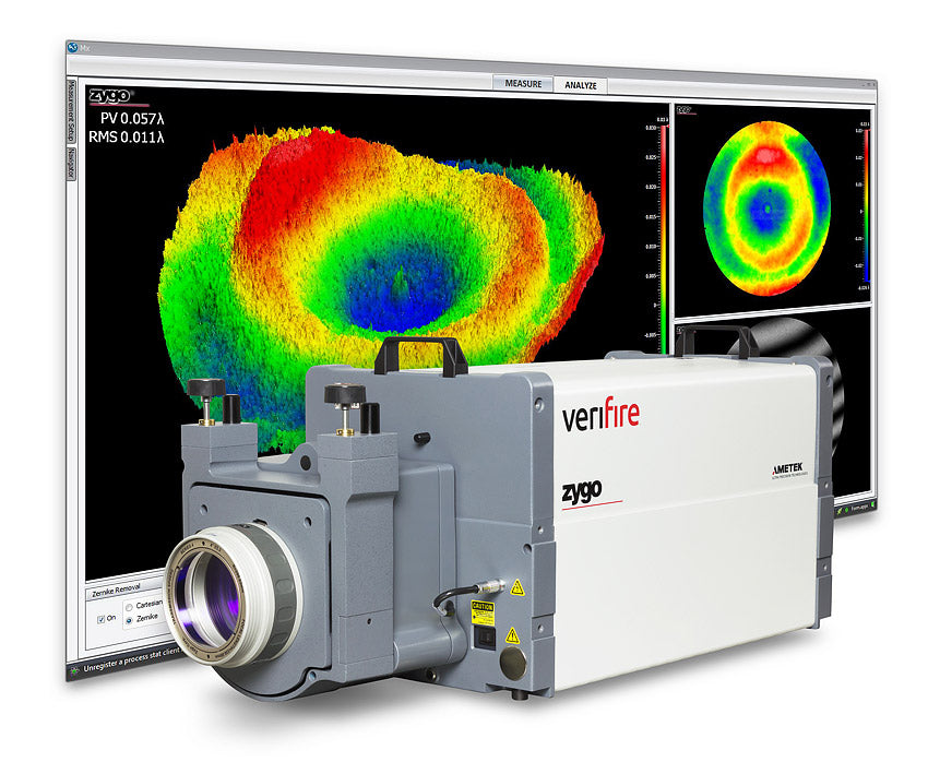
Esco uses a state of the art Zygo Verifire XPZ Interferometer to test the surface accuracy of its optics. Photo courtesy of Zygo Corporation, Middlefield, CT.


Committed to supporting American industry and ensuring the highest-quality production standards.

Esco Optics proudly manufactures precision optics for all branches of the armed forces land, sea, air and space.

Esco manufactures compliant ITAR optics for all of its customers with the strictest confidentiality.

Dedicated to fostering connections, collaboration, and innovation across the optics manufacturing industry.